


So the first task was to read the build instructions that come on the provided disc in PDF format. I also looked at a few build blogs I found on line.
The first task was to join the wing halves with 5 minute epoxy, however I didn't have any, so 30 minute epoxy would have to do.
This is done whilst resting on the wing beds, so I taped the two wing bed panels together firstly.

Then, so as to not stick the joined wing to the beds with any epoxy which might drip through, I placed a piece of grease proof paper onto it, glued the two wing halves together and held them together using masking tape, and weighted it down with my sugar jar.


Once the glue had set, I then ran a length of masking tape along each side of spar groove. The two carbon tubes fit into an aluminium tube, which is slightly wider than the groove and the foam has to be marked and cut to allow this to fit.

There will be a gap at the end of each wing, and so foam from the wing bed has to be cut out to fit the spar slot and glued in place. I used UHU POR for this.

I then ran Gorilla Glue along the whole length of the spar grove and fitted the spar. I then covered this with more grease proof paper and weighted the spar down with tins of baked beans, tomatoes and whatever else I had in the kitchen cupboard and left it to dry overnight.
Upon inspection this morning, the Gorilla Glue had seeped through the foam and slightly stuck it to my building board, but this was easily prized off.
I only used a small drizzle of glue as it expands into a foam, but only a little of it had come up the sides of the carbon spar tube.
This evening I poured epoxy over the top of the carbon spar tubes and fitted the balsa spar cap filler strips.


In the mean time, whilst glue has been setting during the above tasks, I made a start on the fuselage.


The carbon tube longeron supplied is glued into the slot which runs almost the full length of the bottom section. Enough epoxy is supposed to be mixed so that the glue is pushed up the sides of the longeron and then fill the gap above to the fuselage top, totally encasing the longeron in epoxy. However, I'm trying to keep this build light so I only used enough epoxy to glue the longeron in place. It's certainly secure enough!

I then made provision for adding a switch as the hole for this was going to be easier to make before the fuselage top was glued to the bottom section.

Instead of the recommended epoxy, I glued the two halves together using UHU POR, which is more elastic in nature, epoxy is quite brittle and I'd rather there be a little give there.
In the picture above, you can see there is a slot in the nose where the longeron ends. This slot is filled with a supplied piece of foam dowel and just glued into place.

Once the glue has dried, the shaping of the fuselage can begin by using a blade to shave off 3mm of foam from each corner and then sanding smooth and to shape.

I couldn't resist putting the wing into the fuselage for a cheeky look.

So the next jobs are to shape the wing tips and add the rear wing spar before looking at fitting the servo's.
I've read on one of the forums that it was recommended to make a ply box to fit the servo's into as over time the foam around a potted servo compresses and makes the servo loose. This is something I haven't experienced before with an EPP model. Usually what I do is wrap the servo in masking tape and use a large blob of hot glue to secure it in position, so that the glue comes up the sides of the servo, the servo then is secure and doesn't move, but also, by using the hot glue, the servo is easily prized out should the need arise.
This is something I shall have to think about, but my instinct is to use my tried and trusted method.
---------------------------------------------------------------------------------------------------------------------

Then I had to fit the rear carbon spar. This was achieved by measuring 3" down from the main spar, laying the rear spar on the foam and drawing the outline of the spar onto the foam. I then used a blade to cut the outline and a router type tool to remove the foam. I chose to use Gorilla glue instead of epoxy to glue the spar in place. The instructions say to use epoxy and then use scraps of balsa to fill any gaps, but by using the GG the glue filled any gaps instead.
The next job was to decide where to fit the servo's. The instructions recommend they are mounted up against the main spar, which makes sense! So I marked the foam and routered it out until the servo's, when fitted, were flush with the top surface of the wing.
The servo's were then potted. I mixed up some epoxy and used just enough the cover the walls and bottom of each servo bay. The servo was then placed in a polythene sandwich bag and pushed into the tight fitting bay and left to set. The servo was then taken out, removed from the bag and then I wrapped the servo in masking tape and secured the servo in place with a blob of hot melt glue.

The instructions say to fit the servo's so that the servo arms and control rods lay UNDERNEATH the wing. I have to say I do not like this idea. I guess it's fine if you are landing on a crown bowling green, but very few slopes are that smooth. Most of the UK forum builds I've looked at have put the control rods ABOVE the wing, and that is what I have done. This has meant I have had to take the servo wires over the top of the spar, but they should be ok.
So that is the wing now completed and ready to be mated with the fuselage, which will happen one I have made the RC component bay, which is my next job.


Next up a job I've grown to really enjoy doing, laminating, or NS (new stuff) as some still call it.
There are a lot of people who think that you need to use some kind of spray glue, such as 3m 77 for the lam to stick down properly, but that has never been my experience and this is the 5th model I've laminated and I have never felt the need to use any extra glue to hold down the lam, which sticks down perfectly well by itself.
I do each of the four wing panels separately and cut the lam about 25mm (1") oversize, then I set the iron at 120*c. I begin in the middle of the wing and work outwards, then iron the overlapping bits over the LE and TE. This gives a double layer once you've completed the top and bottom to protect the LE from damage. Once the lam was down I reset the iron to 150*c and went over it again. This tightens it up and removes any wrinkles. If it's been done correctly, it should look like a glass finish.

I had marked the wing during a dry fit to show the position of the fuse and I laid onto the wing, (both top and bottom surfaces), two strips of 1" (25mm) masking tape. This is to stop any glue that should be squeezed out of the fuse from sticking to the wing itself.
The wing was pulled out of the fuse by about ¾" (20mm) and a generous dollop of UHU POR was squeezed onto the wing and spread around, both on the top and the bottom. The wing was then pulled back into the fuse and then out the other side and the process repeated, so there was plenty of glue to stick the wing to the fuse.

--------------------------------------------------------------------------------------------------------------------------
The next job was to take the supplied elevons and create a bevel on the ¼" TE end, for this I used a razor plane and finally a light sanding. The elevons were then cut to length and the tips shaped as per the supplied template before being wrapped in 75 micron laminate film, which really stiffens them up.

The elevons were then attached to the wing using 1" (25mm) X weave tape and then a hot iron used to really stick them down.

Before I glued the wing to the fuselage, I decided it would be a good idea to ensure the servo's actually worked. Really I should have tested the servo's BEFORE I fitted them into the wing. So I found a spare receiver, set up the Moth on my transmitter, and bound the RX to the TX, and fortunately all worked ok. However, when I tried to fit the RX into the electronics compartment, it was too big and wouldn't fit.
I usually use the Hobby King AFHSS Hitec Minima compatible RX in my models as they are really cheap, but I haven't had any problems with these at all. So an alternative had to be found.
I was thinking of using a original Hitec Minima RX, but after posting my issue on the BARCS forum, a alternative product was advised, a Frsky AFHSS Minima compatible unit available from T9 Hobbysport. This isn't a full range unit, but it does have a range of 1000m, so this would be perfectly adequate, after all, this model is designed for fast passes along the slope, so I'll be lucky if it gets 500m away from me.
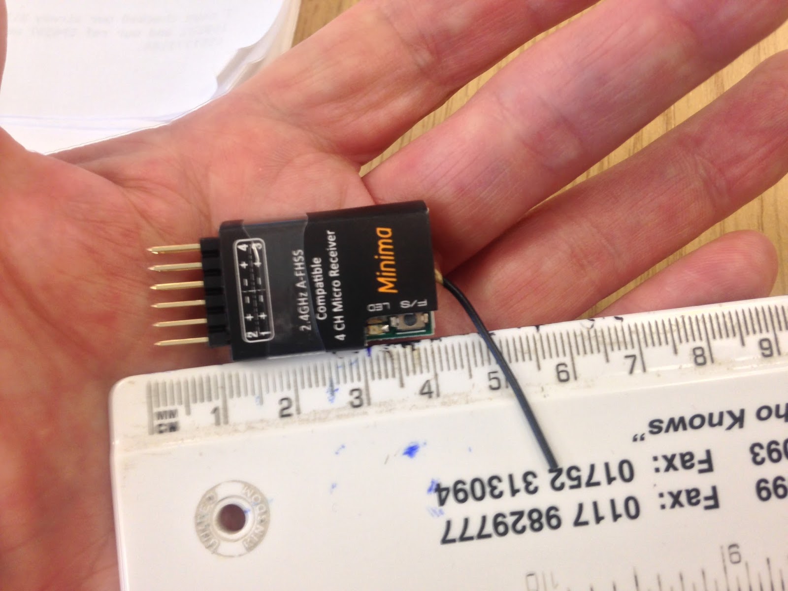

I connected it up to the Moth, bound it to the TX, and it slides into the cavity very nicely.
I have been informed that the stumpy aerial has a habit of coming away from it's connection, but that a small blob of hot melt glue stops that occurring, so I will have to do that.
--------------------------------------------------------------------------------------------------------------------------
The kit provides two pieces of balsa which have to be glued together. Then the supplied template is laid on top and the balsa cut to shape. The template shows where the balsa join line should be and the direction in which the wood grain should run. Simple!
Except it wasn't simple! I laid the the balsa on top of the template to gauge the position of the grain and join line.

As you can see, there was more template than balsa. So I tried another way.

Nope, that wasn't going to work either. So it appears that NCFM have provided an incorrect size of balsa. And yes, the template did print at the correct size because it also included the wing tip template, and that was perfect.
So my choices were to use the supplied balsa, make the fin smaller and with the grain running vertically instead of at an angle or, make a new fin out of my own stock of balsa sheet. And that was what I decided to do.

And this is how it should have turned out with the supplied balsa.
So with the fin made, the next job was to cut a groove in the top of the fuselage for the fin to sit in. I measured and then used a blade to cut through the X weave tape and foam all the way down to the carbon longeron before widening the cut with a router type tool.
I then mixed up some epoxy and smeared the walls and floor of the groove with the glue. The fin was wrapped in a plastic bag and then inserted into the groove and left it there whilst the glue set.
I removed the fin and plastic bag from the groove and just added a strip of 1" (25mm) X weave tape along the bottom of the fin before inserting it back into the groove.
The fin isn't meant to be fixed in place, in case it has a mid air collision or dodgy landing, in which case the fin can be easily replaced. But the instructions do say you can use some clear tape just to ensure the fin remains in place during normal flying.

So the build/assembly stage is now complete and I'm ready to begin covering.
--------------------------------------------------------------------------------------------------------------------
So the wings were covered in shrink film from Hobby King, and the fuselage in Solartx. It's the first time I have used Solartex and I was really impressed at how easily it went on.
Once it was covered, I then gave the wing a second covering of 42 micron laminate film. This will protect the shrink film from the course vegetation on the slopes when landing. I'd noticed a few small nicks and tears in the film on the Polecat, so I'll be giving the Polecat the same treatment later.
And the final weight? 21 1/4oz
Hopefully the weather will be kind this weekend so I can get out and maiden her, we'll see.


--------------------------------------------------------------------------------------------------------------------
This took place on the Back of Wrecker at the Bwlch. On arrival, the cloud was very low, and sometimes low enough to engulf us in what the locals call, "clag".
A few of my flying buddies would be a bit hesitant about performing a maiden flight on Back of Wrecker. Out of all the slopes at the Bwlch, it is our least favourite, suffering from turbulence caused by the forest below, the patchy lift it sometimes produces, and the fact that if it all goes wrong, it can be difficult to retrieve your model as the cliff is almost vertical with a road at the bottom.
But we had about 17 mph of southerly wind, and I'd already sent up the Wildthing to test the air, so on I went.
I headed up to the brow behind the slope and gave the Moth a few test throws and found I had to add a few clicks of up elevator trim.
Mark did the honours for me and threw the Moth, but it nose dived straight into the ground. A few more clicks of elevator trim and Mark tried again. It probably helped that this time he was also standing closer to the edge of the slope as this time it went away without a hitch.
Due to the low cloud I had to keep the Moth low and cruise back and forth only. So now happy that she was trimmed, I decided to bring her in as the clag was beginning to come in and soon I wouldn't be able to see it.
Mark, Mike and myself hung around for a while, and eventually the skies cleared and I was able to launch her again, and she flew beautifully.
So now I just have to play about with the CofG until I find the "sweet spot".
Enjoy the video.
I always enjoy reading these slope racer builds Steve. I'll check in for the next instalment.
ReplyDeleteThanks, glad you're enjoying it.
Deletehi there very nice could you help i am looking at the ncfm m60 if i wanted to put a ballast tube in were would it go one in each wing or fuselage
DeleteNice
ReplyDeleteCheers Mark
ReplyDeleteNice to see it finished and flown Chuck Glider.
ReplyDeleteI've got a wabbit, half pipe, and half bad from NCFM and been thinking of buying a moth to add to the fleet. Your build thread was very helpful. Much appreciated.
ReplyDeleteChris
I've just bought the Moth and found your blog very useful, I can't get some of the glue products mentioned so I will be using slow and fast setting epoxy has I did with my other epp models without any problems, these include the Bat & Wicked which i've had for several years without problems thanks again for a great blog .
ReplyDeleteHi Tiggyfox. I'm glad you found my blog useful, that is what it is there for. A word of advice, do not place the elevon control rods on top of the wing as I did, they work much better on the underside as per the instructions.
ReplyDeleteMy "sandwich" method of covering works very well too, and it has been remarked by others that my models that I have covered in this way appear to fly slightly faster than traditional covered models.
Let me know how you get on.
Steve
Hi Steve, I've got one of those little 4ch Minima compatible receivers - I haven't used it yet - is yours OK? Interestingly, I came across a 6ch full range Minima compatible Rx (Ikonnik KA-6) on Ebay today for £13.00 with free postage! https://www.ebay.co.uk/itm/273036162111.
ReplyDeleteHi Russell. The 4ch Minima compatible RX is rock solid with my TX and I've experienced no problems at all. They are great in the tight confines of a small foamie where you're going to be flying it close to yourself, remembering that the range is about 900m. I also use the 8ch compatible ones also in most of my other other models and I haven't had any problems with those either.
ReplyDeleteAbsolutely brilliant build instructions (would have like a bit more about the fus covering - number of pieces and how you went about it just for my own benefit). You have definitely got a gift for explaining things first time I have been able to read something straight through without numerous re-reads and going back and forth. Well done on a great build and brilliant write-up
ReplyDelete